The fibres of the CN II run from the retina to the optic chiasm, where the fibres from the nasal retina cross. The fibres continue along the optic tract to the lateral geniculate nucleus, where a synapse is located. The stimuli are then projected via the optic radiation onto the visual cortex [Figure 3].
If a patient complains about their vision or if, for some other reason, you wish to examine the function of the visual pathway, first check whether the refractive media (cornea, anterior chamber, lens, vitreous humor) are intact and whether the patient’s vision is optimally corrected.
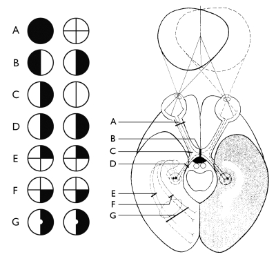 Figure 3
A
Lesion of the optic nerve
B
Median lesion of the optic chiasm, with loss of function of the crossing pathways; heteronymous hemianopsia
C
Lateral lesion of the optic chiasm
D
Lesion of the optic pathway (central vision is also impaired)
E & F
Lesions in the optic radiation
G
Lesion in the visual cortexNB: central vision is intact because the stimuli, originating from the central part of the retina after the synapse in the lateral
geniculate nucleus partially cross each other.
NB: central vision is intact because the stimuli, originating from the central part of the retina after the synapse in the lateral
geniculate nucleus partially cross each other.
Assessment of visual acuity
Procedure
- Have the patient stand about 5 or 6 metres away from the eye chart.
- Ask the patient to loosely cover one eye with their hand.
- Ask the patient to look at the chart in a relaxed manner (check that the patient is not squeezing their eye together).
- Instruct the patient regarding the correct nomenclature of the optotypes according to position or significance (Landolt rings, E-signs, etc.).
- Slowly point to the optotypes one by one, starting at the top row.
- The row which the patient can just read without error and hesitation should be taken as the measurement of visual acuity.
The stenopeic hole (pinhole)
- Have the patient stand 5 (or 6) metres away from the eye chart.
- Ask the patient to look at the eye chart through a small pinhole (the stenopeic hole) with each eye separately.
- Ask the patient whether their vision improves when they look through the hole.
Interpretation and further examination
The artificial aperture reduction excludes any light scattering and increases the visual acuity. If the vision does not improve there is no refractive abnormality. In this case, you will have to investigate whether the condition is one involving the retina or a nerve.
Vision should be determined by dividing the distance from which the patient can read the row (d) by the distance from which a person with the standard visual acuity of 1(D) can read the row (d/D). On some charts visual acuity is indicated at each row; on others the ‘D’ distance is shown.
If a vision of 1 (d/D) is not achieved, have the patient look through a pinhole and see whether this improves the vision. If this is the case, the correction was not optimal.
Then investigate the vision in the other eye.
- If the patient cannot read the top row of the eye chart (vision <5/50), you should examine their visual acuity by holding up your fingers in front of a white background. With a visual acuity of 1, you should be able to hold up your fingers 60 metres away from the patient, D = 60. Now determine at which distance the patient can see how many fingers are being held up.
- Examine each eye separately.
- If the patient cannot even see the held up fingers at a distance of 1 metre, test whether the patient can see movements of your lower arm or hand. With a visual acuity of 1, this should be visible at a distance of 300 metres (D = 300).
- If the patient cannot even see this at a distance of 1 metre, determine whether they can perceive light. If they can perceive light, the visual acuity is 1/ ~. If there is no light perception, the visual acuity is 0.
The pupils
Direct and consensual reaction to light.
In the case of pupillary light reaction the CN II is the afferent pathway and CN III is the efferent pathway.
Procedure
- Inspect the pupils and take note of their size and shape [Figure 4].
- Compare left and right.
- Place a hand between the patient’s eyes.
- Ask the patient to look at a fixed point in the distance.
- Shine a light onto the pupil from the side. NB: the patient must not look at the light and the light source must be sufficiently powerful.
- Note both the direct reaction to the light (constriction of the pupil on which the light is being shone) and the consensual reaction (constriction of the other pupil).
- Next shine the light on the other pupil and note the direct and consensual light reaction.
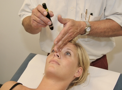 Figure 4
Procedure for examining the peripheral field of vision
(confrontation method)
- for this examination you should sit facing the patient with your knees almost touching those of the patient. Your eyes should be at the same level as those of the patient.
- ask the patient to close the left eye or loosely cover it with their hand (if necessary you can use an eye patch to cover it). You should close your right eye (if you are not able to close one eye properly, you can use an eye patch). Place your hands in an imaginary plane (a, b, c, d) between your knees and those of the patient; the distance between this imaginary plane and your eyes should be almost the same as to the eyes of the patient. The cross-section between your field of vision (p o’ q) and that of the patient (p o q) should therefore fully overlap in this plane [Figure 5].
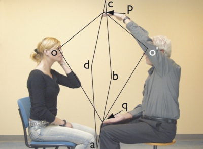 Figure 5
- you should now move both your hands out to the side until you can just still see them. Next, you should move both hands little by little circumferentially along the periphery of the field of vision [Figure 6]. When doing this, you should alternate between making small movements with your fingers of one hand or both hands together and ask the patient to indicate on which hand the fingers are moving.
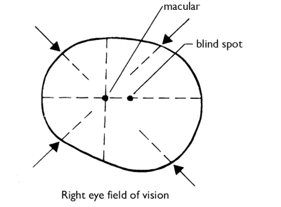 Figure 6
- next, place one of your hands in about the middle of the boundary of the temporal upper quadrant of the field of vision, and the other in the middle of the nasal lower quadrant. From here, you should move both hands, again alternating between moving the fingers of one of your hands or of both hands together, to the middle of the visual field. The patient should indicate again which fingers they can see moving. Finally, repeat the procedure but this time starting from the temporal lower quadrant and the nasal upper quadrant. The horizontal and vertical line in the field of vision should be investigated in the same manner.
- next, examine the other eye in the same way. The other eye should also be covered.
Ophthalmoscopy
To obtain a clear image of the fundus of the eye, amongst other factors it is important that the pupil is sufficiently dilated. This can be achieved by putting a drop of a mydriatic agent in the eye. If you need to assess pupillary reactions (for example in a comatose patient), the use of a mydriatic agent is contraindicated. If the patient suffers from glaucoma or angle closure glaucoma of the anterior chamber, you should put a drop of pilocarpine into the eye immediately after ophthalmoscopy to counteract the effect of the mydriatic agent.
Procedure
- Dim the lights in the examination room.
- Turn on the ophthalmoscope.
- Set the C/F (cornea / fundus) dial to F.
- Adjust the lens dial (= algebraic sum of the patient’s refractive error and that of the examiner)
- Inspect the eye with the light beam in the ‘full moon’ setting.
- Ask the patient to look over your right shoulder at a point in the distance.
- Position the ophthalmoscope in front of your right eye and allow the light to shine into the patient’s right pupil from a distance of 15-30 cm [Figure 7].
- If you define the patient’s visual axis (i.e., the imaginary axis that runs straight through the centre of the pupil) to be the 0 axis, you should be looking up at the patient’s eye at a temporal angle of about 15° to this visual axis.
- If there are no optic media opacities, you should see the patient’s pupil in a reddish-orange glow.
- If the lens dial is properly adjusted, you should already see small vessels and / or the optic disc illuminated.
- Hold your index finger against the lens dial so that you can adjust it if the image is out of focus.
- Now approach the patient’s eye from a temporal 15° angle.
- Assess the retina and the optic disc.
- Next, examine the patient’s left eye.
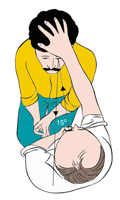 Figure 7
If you are not successful in carrying out ophthalmoscopy with your left eye, ask the patient to lie on the examination table. Stand at the head of the table and from this position you will be able to carry out ophthalmoscopy on the patient’s left eye using your right eye [Figure 8].
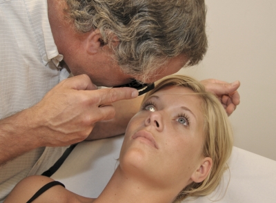 Figure 8
Interpretation
To properly interpret the image of the fundus, it is not only necessary to properly master the technique so that you can inspect the entire fundus, it is also important to have examined many fundi or pictures of fundi.
You should know what optic disc oedema looks like when caused by increased cranial pressure and when caused by ischaemia or retrobulbar neuritis.
A normal optic disc has the following characteristics:
- The colour around the edge is light yellowish-orange to light red and pale
yellow / white in the centre (this is the excavation). - The border is defined and regular, more marked temporally than nasally.
- It is oval to round in shape.
- The cup/disc ratio is 0.4 (the critical limit is 0.6).
- The optic discs should be symmetrical.
You should know what preretinal bleeding looks like as this may indicate a subarachnoid haemorrhage. For the various fundus images please consult a good atlas, such as that written by Bedford (refer to literature list). If you do not feel capable of interpreting abnormal images, make sure that at the very least you are able to recognise the normal situation so that you can call on a more experienced examiner in the case of any abnormal findings.